
Knowledge · Fundamentals
Photogrammetry: from photo to 3D model
How overlapping drone photos become a measurable 3D model: image orientation, point cloud, terrain model and orthophoto, explained on a real flight.
Published · 7 min read · by Markus Linke
Photogrammetry is the method by which many overlapping photographs become a true-to-scale, three-dimensional representation of a site. No sensor measures a distance in the process. The geometry lies solely in the images, and the software extracts it by comparing the same points on different exposures. This article follows the path from the shutter release to the finished model, using the figures from a real flight.
The basic principle: depth from two viewpoints
Two eyes see in three dimensions because the same object is imaged slightly displaced on the two retinas. That displacement, together with the known distance between the eyes, gives the range. Photogrammetry does the same, only with one camera in many positions instead of two eyes in one.
For that to work, every point on the ground has to be visible on several images. That is why the drone flies in parallel lines and triggers the shutter often enough for consecutive images to overlap heavily. On the landfill flight, which we look at in detail below, it was 92 per cent along the flight direction and 85 per cent between the lines. A point in the middle of the area therefore appears on more than ten images from different angles.
This redundancy is not a luxury. It is the reason the method is robust against individual poor images, and the reason the software can decide at all which point correspondence is correct.
Step 1: where did the camera stand?
The first computing step is called image orientation, or structure from motion. The software looks for distinctive image features in each photograph — corners, edges, texture patterns — and finds the same features again in the neighbouring images. From thousands of such correspondences it computes two things at once: the position and viewing direction of every single camera, and a first, still sparse point cloud.
This is where georeferencing comes in. Our drones carry an RTK receiver that knows the position of each shutter release to within a few centimetres. Without RTK the model would be internally consistent but would sit somewhere in space and would have to be fitted using ground control points. With RTK it sits in national coordinates from the outset.
A side effect of this step: the software calibrates the camera as well. Lens distortion, focal length and the principal point are estimated from the data itself instead of being assumed as known.
Step 2: the dense point cloud
The point cloud from step 1 contains only the distinctive features, so a few tens of thousands of points. That is far too coarse for a usable model. In the second step the software therefore computes a depth for practically every image point, by comparing the images in pairs and merging the results.
From 443 photographs, 384 million points were produced in this way, each with a position in three dimensions and the colour from the photograph. That is the real body of data: everything that follows is derived from it.
Step 3: separating ground from non-ground
A raw point cloud knows no difference between soil, vehicle, bush and container. For volumes and terrain shapes, however, exactly that distinction is decisive. A ground classification therefore runs over the cloud, in our case with the SMRF method, which lays a progressively finer sieve over the points and sorts out everything that sits too abruptly above its local surroundings.
Two elevation models come out of this:
- DSM, the surface model, with everything that stands on the ground.
- DTM, the terrain model, the ground itself only.
The difference between the two is, incidentally, exactly what a volume calculation evaluates.
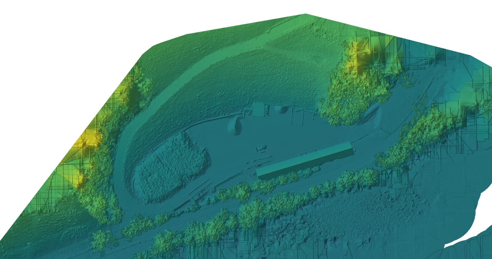
Step 4: mesh and orthophoto
From the point cloud a triangular network is computed, the mesh, and over this network the original photographs are laid as a texture. The result is the navigable 3D model that you can rotate in the browser in the showcase.
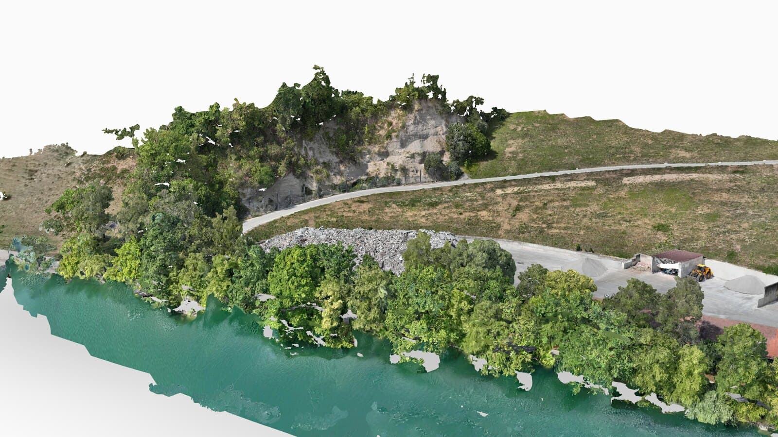
For the orthophoto, the software projects each photograph back onto the elevation model and assembles the rectified images into a seamless mosaic. Because the rectification uses the elevation model, the quality of the orthophoto is directly coupled to the quality of the point cloud. A poorly reconstructed roof shows up in the orthophoto as a smeared edge.
What determines the accuracy
Three quantities that are often confused:
- Ground resolution — how large one pixel is on the ground. Depends on flying height and camera. On the landfill flight, 1.6 cm at 68 metres above ground.
- Relative accuracy — how well the model is internally consistent. Comes from overlap, image sharpness and texture.
- Absolute accuracy — how well the model sits in national coordinates. Comes from the georeferencing.
For the RTK level without ground control points we commit in our quotation to five centimetres in position and ten centimetres in height. The processing report of the landfill flight states around three centimetres absolute. That figure is the expected value of the method with an RTK fix, not the result of an independent check: no ground control points were laid out on the flight, and therefore no check points were surveyed against which the model could have been verified. If you need a demonstrated accuracy, you book the level with surveyed ground control and check points; there the measured deviations are stated in the report.
Where the method reaches its limits
Photogrammetry needs texture. Where the image offers no distinguishable features, the software finds no correspondence:
- Water surfaces deliver only reflections and do not reconstruct.
- Fresh snow, bare sand, new asphalt surfaces are too uniform.
- Glass and bare metal roofs reflect differently depending on the viewing angle.
- Dense vegetation conceals the ground completely.
- Hard shadows and changing cloud during the flight create image differences that have nothing to do with geometry.
Most of this can be defused by planning: even light, a sun angle that is not too low, calm wind, and where necessary additional oblique images at critical edges. What cannot be defused is stated in the report.
The landfill flight in figures
An active landfill on the Swiss Plateau, flown on 1 August 2026 with a DJI Matrice 4E:
- 7.0 hectares of area, relief from 428 to 533 metres
- 68 metres above ground, 92 per cent forward and 85 per cent side overlap
- 443 photographs in seven minutes of pure flight time, 1.6 cm ground resolution
- Georeferencing by RTK fix, no ground control points, around 3 cm absolute according to the report
- 384.3 million points, from them DSM, DTM, textured mesh and orthomosaic
- 24 gigabytes of data in total, processed with OpenDroneMap in ultra mode
Those seven minutes of flight time are the tip of a full working day: the drive, the walk over the site, mission planning, setting up, the flight, packing up, then the processing and the checking of the results. The showcase shows the original data in the browser.
What this means for your project
You do not have to carry out any of these steps yourself. What matters is only what follows from them: the quality of the delivery is decided on the day of the flight, not at the computer. Overlap, flying height, light and the question of whether ground control points are needed determine what is possible in the end. That is why we ask about area, object and purpose when you enquire, before we propose a date.
How a project runs and which deliverables it produces is set out on the drone surveying page.
Frequently asked questions
- How many photos does one hectare need?
- As a rough guide, 50 to 80 photos per hectare at 1 to 3 cm ground resolution. Our landfill flight produced 443 photos for 7.0 hectares, so a good 60 per hectare. The exact number depends on flying height, overlap and the shape of the terrain: broken relief needs more images than a flat area.
- Why is the drone's position alone not enough?
- The drone knows where it was, but not what the terrain looks like. The shape only emerges from the overlap: the same point on the ground has to be visible on several images from different angles before the software can compute its position in space. The RTK position then ensures that this model sits in the right place in national coordinates.
- Can photogrammetry see through vegetation?
- No. It only sees what was photographed, that is, the surface. Under a closed canopy the ground stays invisible. With sparse growth, ground classification helps: it separates points on vegetation from ground points and computes a terrain model from them. For forest under leaf you need laser scanning.
- What is the difference from a laser scan?
- Photogrammetry computes geometry from photos and necessarily delivers colour with it. A laser scanner measures distances directly and reaches the ground through gaps in the growth; it only delivers colour if an RGB camera flies with it and the point cloud is coloured afterwards. Laser scanning costs considerably more. For open areas, construction sites, landfills and roofs, photogrammetry is the cheaper and usually sufficient choice.
- How long does processing take?
- The processing run for a dataset of this size takes a few hours on our GPU cluster and runs unattended. What determines the delivery date is not the computing time but the checking afterwards. As a rule we deliver within a week of the flight.